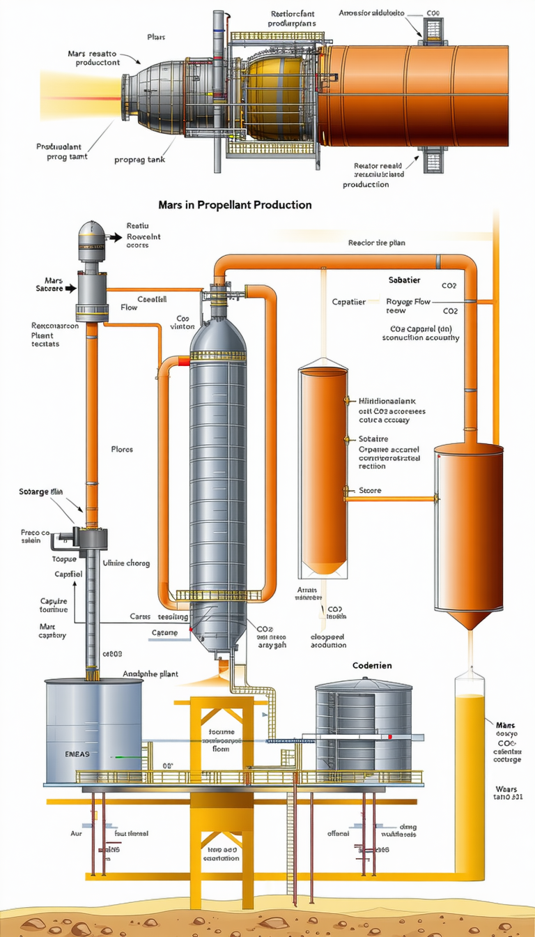
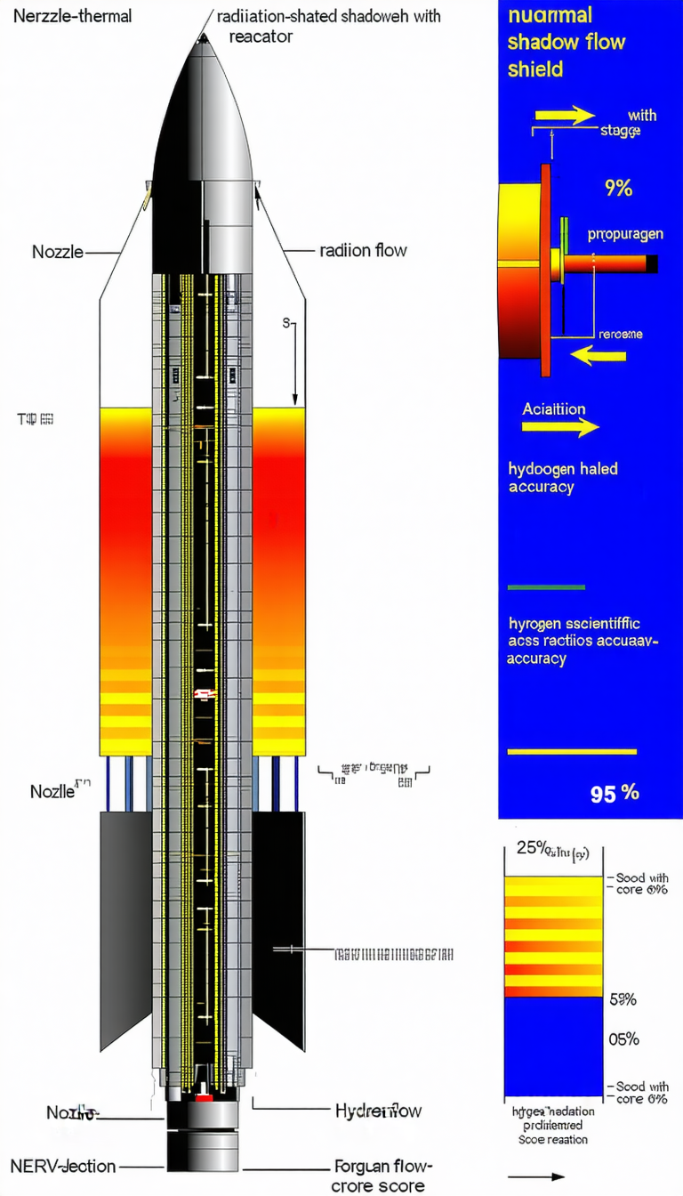
The Image Is A Diagram Showing The Process Of A Thermoelectric Cooler
Description
The image is a diagram showing the process of a thermoelectric cooler. The diagram is divided into several sections, each with a different function. The first section is the heat source, which is the red part of the diagram. The second section is the heat sink, which is the blue part of the diagram. The third section is the thermoelectric cooler, which is the yellow part of the diagram. The fourth section is the heat exchanger, which is the orange part of the diagram. The fifth section is the radiator, which is the green part of the diagram. The sixth section is the heat sink, which is the purple part of the diagram. The seventh section is the heat exchanger, which is the pink part of the diagram. The eighth section is the radiator, which is the white part of the diagram. The ninth section is the heat sink, which is the yellow part of the diagram. The tenth section is the heat exchanger, which is the orange part of the diagram. The eleventh section is the radiator, which is the green part of the diagram. The twelfth section is the heat sink, which is the purple part of the diagram. The thirteenth section is the heat exchanger, which is the pink part of the diagram. The fourteenth section is the radiator, which is the white part of the diagram. The fif